Case Study: Gulf Coast VPL / Wheelchair Porch Lift Installation
ASAP Lifts was contacted to provide a solution for a coastal homeowner to improve accessibility to their elevated-style coastal home and help the homeowner avoid stairs.
The most affordable solution would have been to add an outdoor stairlift that typically starts around $5-7K, but this wouldn’t be ideal due to an overhang partially over the staircase, narrowing the stairs a bit. Also, the slope of the stairs was just too shallow for us to place an outdoor stairlift incorporating a aircraft-cable and drum carriage as those typically require a minimum 35º slope to avoid triggering the slack cable e-brake on the unit if the carriage encounters any debris in the rail or the rider isn’t as heavy and there isn’t enough tension on the cable. Also, the customer wouldn’t be able to park a mobility device or use that on the upper landing in the event it is necessary.

Wood steps leading up to Gulf Coast home’s second story porch.
The next-best solution would be a vertical platform lift. But before we could place this, we had to determine the best location working with the existing structure to minimize pre-construction costs, avoid overhead lines coming into the area and provide a stable foundation for which to incorporate a run-up to the lift and serve as the lift’s installation base.

View of deck from rear of home facing road for full view of deck and support.
The Evaluation:
We evaluated for a space to place the lift to allow room for entry and exit. We lucked out when two of the existing railing structures left just enough space to place an interlocked gate at the top landing. The opening was just at about 48” wide, which would be sufficient for a proper 42” landing gate if we shimmed one of the vertical supports with a 1” thick piece of 5/4 board sistered-in.
Had this not been the case, we would have had to reflowed at least one of the railing openings by cutting down a support flush with the deck landing, then notching a new vertical support to provide adequate enough strength to mount to the supports underneath the floor of the deck to serve as a new vertical post. Having the opening already large enough to sufficiently place our gate helped shaved costs associated with modifying the decking.
We pretty much knew concrete would be necessary. Originally, we wanted to go to the left of the rear deck with a straight entry into a carriage just off the parking area that would exit onto the deck above, but the run-by area that the unit travels vertically would have interfered with power feeding into the home, or at minimum would have put the user in close proximity to those wires. relocating the utilities would have been expensive, so we decide to move the installation to the rear-most part of the deck. This would add some concrete needed and pose for a less than ideal streamlined approach given we would have to work around underground utitlities and the home’s piers as well as the deck’s existing structural supports, but by enlarging the pad a little, it would provide enough room to put the user beyond the deck to bring it up and down and enter the platform.

View of underside of deck/approach to opposite rear-side of deck
Again, the idea was to shave costs and work with the already-existing arrangement to streamline complexities in relocating utilities, building extensive walkways out of concrete, etc.
Another consideration was power for the deck. The Vertical Platform Lift runs off a normal 120V household circuit, but we wanted to use a dedicated 20Amp breaker and introduce a fusible disconnect as called for by the manufacturer to serve as a cut-off for the unit’s power in the event a reset is needed or a technician has to service the unit and needs to easily ensure power is cut off for safety reasons. Also, the fused disconnect helps protect the on-board circuit board that controls the lift. Fortunately, the client’s existing panel allowed for this expansion and we brought in a local area electrician to add this component.

The disconnect installed by the electrician serves as a fused cut-off for the unit. Inside, there are two poles: one for the unit’s main AC power fed from the panel, and the other cuts the unit’s DC backup circuit.
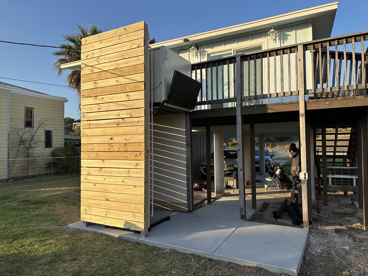
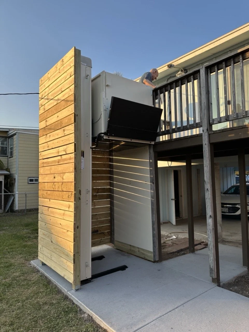
Another consideration was that the lift needed to lift over 8’, vertically in order to reach flush to the top landing. We would need a 10’ tower as we typically want to avoid completely maxing out vertical travel and an 8’ tower would have left us short about 2-3”. Likewise, to save space and concrete, we would want the user to enter the bottom straight on, but exit 90º to the right at top. As such, we couldn’t place the lifting-tower directly adjacent to the existing deck, which posed a problem for adding braces to cut down on tower sway. Also, because if the unit’s proximity to the shore, the area is known for high winds and coastal VPLs can certainly be subject to a lot of wear imposed by the environment.
To approach this problem, we decided to build additional support off of the existing deck by adding a slatted wind-wall to:
Provide additional structure to mount bracing to.
To help break high winds directly to the tower coming off of the shoreline.
Make it more aesthetically pleasing.
Help provide some shade to the user in the afternoons.
Enclose the hoistway to a degree while keeping the application affordable.

Early initial sketch of plan. Bottom control was relocated and once we determined the wider top landing gate would fit adequately, we bumped that from 36” to 42” width giving the user more room to make a RH exit off of the platform.
The last evident challenge would be how to get the unit into the back of the yard. We initially consulted a crane service, but the crane op alone well exceeded $2K in additional cost to unload the unit from a trailer in the front of the property and lift over the home into the back yard and onto the pad. We ultimately figured enlisting local manpower and maneuvering the trailer into position by entering the backyard through a very narrow opening between the side of the home and fence. Luckily, we didn’t have to take down any fencing, but it did take some time to finesse the trailer to where we needed it to unload directly off the trailer and erect upright (twice we had to cut off the truck to give the transmission a break from all the maneuvering with the load on the trailer.) This was done by breaking down the unit to its skeleton and removing all the cladding to cut weight, and carefully standing up with the help of some local manpower we enlisted for help. We also managed to keep from obliterating the lawn by moving carefullly.
The Result & Take-Away
The lift resulted in a success. Working remote with concrete and electrical subs, we were able to get the slab poured to allow adequate time for curing, prior to receiving the equipment. The concrete contractor poured thicker footings to the side where the equipment was to be placed. Concrete requires a 4” slab at 4000 psi, but our contractor recommended a 6” thick slab to allow for plenty of ‘meat’ for the 1/2” anchors to be used to attach the base of the tower to the pad and allow for a more level surface with the existing parking area underneath the home.
We were able to keep pre-construction costs in check with a budget at around $11K for materials, subs and labor. This figure doesn’t include the equipment cost, which runs about $27K* (equipment MSRP, including installation) and includes:
10’ Highlander II VPL Tower (MSRP $17,270)
42x54x42” 90º platform configuration (MSRP $1,655)
42” auto-folding ramp (MSRP $125)
1 wired remote call/send stations (MSRP $310)
2 vertical support braces for the tower (MSRP $355/ea.)
42” Landing Gate with incorporated electric interlock mechanism and up/down call/send (MSRP $2,315)
42” platform/carriage gate with incorporated electric interlock mechanism (MRSRP $1,965)
Outdoor Board Config (MSRP $275)
Oversized Freight ($900)
2 Fascia Panels for Fascia/Run-by vertical wall (MSRP $520)
White Glove deliver, setup, installation and haul away of materials (included in MSRP pricing)
While this can seem like a significant figure, an enclosed elevator would easily exceed double the cost of the project total, which makes the VPL a bargain by comparison.
*pricing provided as of late winter, 2025
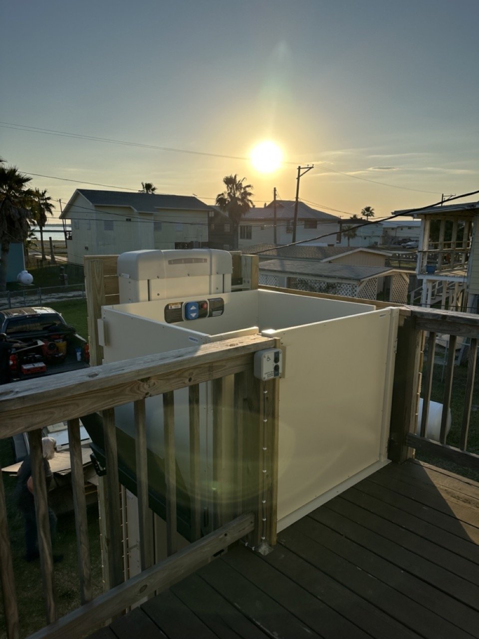
A photo of the completed Vertical Platorm Lift (VPL) installed on the Texas Gulf Coast in late-winter, 2025.
This photo more clearly shows the run-by fascia vertical wall the unit travels along to avoid pinch-points as well as the bottom safety pan underneath that includes a number of switches to sense any obstructions below the unit in the run-by area. Pressure applied shuts down the unit.
The top landing gate fit perfectly with the addition of a shim piece of 5/4” deck board sistered into the existing vertical railing post.
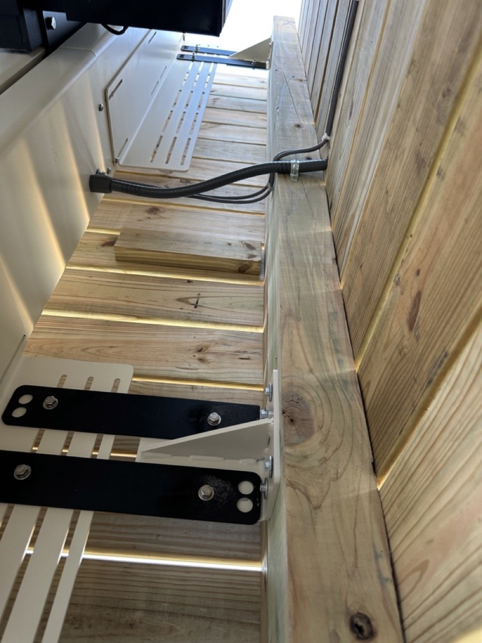
These brackets, shown in the photo, are placed along the side of the vertical tower and anchored into an adjacent structure to add support to VPLs over 6’ of travel. When we go over 8’, we typically like to incorporate two sets of brackets. This helps keep the tower plumb, cuts down on wind interference and reduces movement in the tower when incorporated into higher elevation applications up to 14’. The stock brackets are set up for the normal 36”x 48” platforms. Because this application uses a longer carriage base coupled with more offset due to the way the supports run off of the existing structure, we incorporated pieces of plate steel cut and drilled to custom length to extend the brace.